Technical drawings are of utmost significance in the manufacturing industry as they facilitate the transfer of technical specifications among designers, engineers, and manufacturers.anodized parts turning 5 cnc machining service These drawings hold great importance in the process of creating technical drawings for CNC machining.
To obtain a price estimate for custom CNC parts on the Protolabs Network platform, simply submit a 3D CAD file. The advanced CNC machining systems can directly interpret the part’s geometry from the CAD file, eliminating the need for additional documentation like technical drawings in most cases.
Nevertheless, technical drawings hold significant importance in the manufacturing industry. They facilitate effective communication of technical requirements between designers, engineers, product developers, and machinists. By providing a technical drawing, you can enhance the quality of the sourced parts and potentially reduce costs.This article aims to guide you on when to include a technical drawing or machining blueprints in your CNC order. It will also provide you with valuable insights on what essential elements to incorporate to optimize your part sourcing. Additionally, our engineers will share technical drawing guidelines and best practices to assist you further.The illustration displayed above showcases a meticulously crafted, detailed technical drawing that serves as a valuable reference for maximizing the benefits of this manual. Access a high-quality version of this technical drawing by clicking here, and download the CAD file by clicking here.

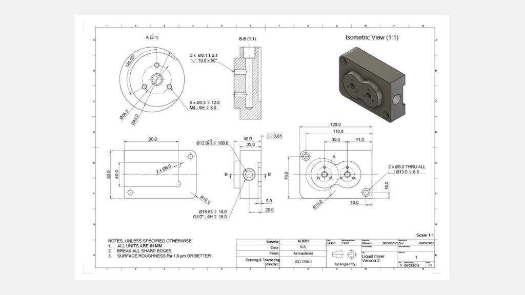
Table of Contents
Technical drawings remain crucial for sourcing parts
Technical drawings
Due to their ability to provide detailed specifications and measurements necessary for manufacturing and assembly processes.parts acrylic fabrication machining plastic cnc ma Technical drawings provide additional information that cannot be conveyed by a 3D CAD file, despite the comprehensive communication capabilities of CAD files with CNC machines. This encompasses various details and specifications that are crucial for the manufacturing process.
- Internal or external threads
- Features with tolerances that exceed the standard
- Surfaces of a particular nature necessitating specific finishing criteria, such as surface roughness.printing parts services cnc lathe machining millin
3D CAD file
It is recommended to provide a technical drawing along with your 3D CAD file when ordering CNC machining, even if your design does not contain these elements.cnc machining center for metal 3 axis The 3D CAD file is commonly used for programming the CNC machine, whereas the drawing acts as a guide throughout the machining process.5 axis machined part cnc machining parts
Furthermore, numerous CNC service providers are capable of directly manufacturing parts based on these CNC turning and milling drawings. In certain instances, we have observed that they even prefer these drawings over CAD files. The aforementioned choice is based on the subsequent factors.cnc machining service plastic cnc machining custom
Certain service providers have the expertise to promptly analyze the geometry of a component based on a 2D schematic. This enables them to easily recognize the primary measurements, functionalities, and crucial characteristics of the part from the 2D diagrams. Additionally, it facilitates a more efficient evaluation of the manufacturing expenses associated with producing the part.
Technical drawings play a crucial role in sourcing custom parts, as they provide detailed specifications and guidelines. There exist numerous standards and best practices for drafting these drawings. As long as your drawing effectively conveys all the necessary technical requirements, the specific drafting techniques employed become inconsequential.
What is the anatomy of a technical drawing?
essential elements
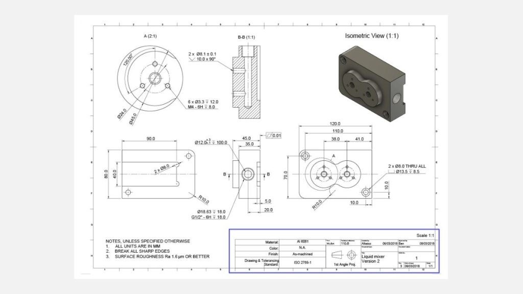
A technical illustration generally includes the essential elements below:
Title block
Isometric/pictorial representation of the component
Primary orthographic views of the component
Sectional views or detailed views
Instructions for the manufacturer.
title block
The title block provides essential details about the part being produced, such as its name, material, finishing and color requirements, the designer’s name, and the company. It is crucial to fill in this information as it informs the manufacturer about the primary function of the part.
In addition to the basic information, the title block also includes technical details like the blueprint scale and the standards used for dimensioning and tolerancing.
Another important element found in or near the title block is the angle projection. This determines how the views are arranged in the drawing. Typically, drawings following ASME standards (US & Australia) use 3rd angle projection, while ISO/DIN standards (Europe) use 1st angle projection. The example blueprint provided in this article follows ISO/DIN standards.
The pictorial (isometric) view
3D pictorial perspectives
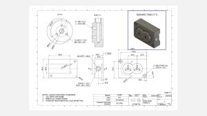
We recommend incorporating one or more 3D pictorial perspectives of the component into your technical illustration. This will enhance the clarity of the drawing upon first glance. Isometric views offer a combination of depth perception and accurate representation of the part’s geometry, ensuring that vertical lines remain vertical and horizontal lines are depicted at a 30-degree angle.
The main orthographic views
orthographic view
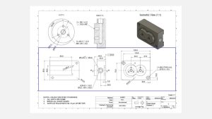
The primary orthographic views provide the majority of details regarding the geometry of your part. These views offer a flat representation of the three-dimensional object, showcasing its precise shape from different sides of a bounding box. By illustrating only the edges of the part, dimensions and features are effectively communicated.In most cases, utilizing two or three orthographic views is adequate to provide a comprehensive description of the entire geometry.
Section views
Technical drawing
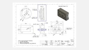
Section views are a useful tool for revealing the internal details of a component. In a primary orthographic view, the cutting line indicates where the part is cross-sectioned, while the cross-hatch pattern in the section view highlights areas where material has been removed.Technical drawings often feature multiple section views, each identified by two letters that connect the cutting line to the corresponding section view (e.g., A-A, B-B, etc.). The arrows on the cutting line indicate the direction of the section.Typically, section views are positioned in alignment with an orthographic view. However, if space is limited, they can also be placed elsewhere on the drawing. The part can be sectioned across its entire width, half its width, or at an angle.
Detailed views
Elaborate view
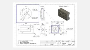
Elaborate views are utilized to emphasize intricate or challenging-to-dimension sections of a primary orthographic view. These views are usually circular in form (positioned off-center to prevent confusion) and are labeled with a singular letter that connects the detailed view to the main illustration (such as A, B, and so forth).Detail views have the flexibility to be positioned at any location on the drawing and may employ a distinct scale from the remainder of the drawing, provided that this is explicitly indicated (as demonstrated in the aforementioned example).
What is the purpose of providing notes to the manufacturer
oem cnc parts
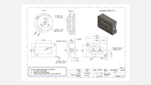
What significance do they hold?oem cnc parts centering machine machining cnc mach.Including notes on the technical drawing is highly significant, even though it is not obligatory for obtaining a quotation. These notes provide supplementary details that were not initially incorporated in the blueprints. These seemingly additional yet crucial pieces of information encompass instructions to remove (deburr) any sharp edges and specific specifications for the overall surface finishing. Moreover, this section of the drawing can be utilized to refer to another CAD file or another component that interacts with the part depicted in the drawing.Notes addressed to the manufacturer frequently employ symbols instead of textual explanations. For instance, a symbol is commonly used to annotate surface roughness.
How to prepare a technical drawing in 7 simple steps
produce high-quality blueprints
Here are 7 essential steps to consider when creating your technical drawing in order to produce high-quality blueprints.
Step 1
Identify the key perspectives and position the appropriate orthographic view at the center of the illustration, ensuring ample spacing for dimension placement.
Step 2
For components with intricate internal structures or challenging areas to dimension, contemplate incorporating section views or detailed views.
Step 3
Integrate construction lines across all views, encompassing centerlines (to delineate symmetry planes or axes), center marks, and center mark patterns (to pinpoint hole centers or circular patterns).
Step 4
Apply dimensions to the CNC drawing, commencing with the crucial dimensions first (further guidance provided in the subsequent section).
Step 5
Define the specifics of thread location, size, and length.
Step 6
Assign tolerances to features necessitating heightened precision beyond standard tolerances. Adhere to ISO 2768, -medium or -fine for metals, and -medium for plastics.
Step 7
Complete the title block and ensure that any pertinent information and requirements surpassing conventional practices (e.g., surface finish and deburring) are detailed in the supplementary notes. Once the drawing is finalized, export it as a PDF file and attach it to your order in the quote builder.
dimensions, annotations, and tolerances
Now that you have acquired a solid understanding of the fundamental framework of a technical drawing, let us further explore the intricacies of incorporating dimensions, annotations, and tolerances.
What is the process for incorporating essential measurements into technical illustrations?
thoroughly dimension
It is highly recommended to thoroughly dimension your technical drawing to prevent any errors during the manufacturing process. However, if you want to save time, you can choose to dimension only the specific features that you want the CNC machining service provider to measure.Here are some tips to help you dimension your models:
overall measurements
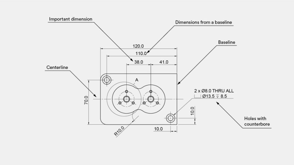
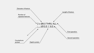
Begin by indicating the overall measurements of the part.Subsequently, include the dimensions that are crucial for functional purposes. For instance, the distance between the two holes in the provided illustration is of utmost importance.Afterwards, incorporate dimensions for other features. It is advisable to align all dimensions from a common baseline, also referred to as a datum, as demonstrated in the given example.The dimensions should be placed on the view that most accurately depicts the feature. For instance, the dimensions of the threaded holes are not included in this view, as they are more clearly described in the detailed view.When dealing with repeated features, only add dimensions to one of them, indicating the total number of times the feature is repeated in the current view. In the example, two identical holes with a counterbore are specified using a 2x in the calloutIf you are interested in delving deeper into the subject of incorporating dimensions into your drawings, I recommend taking a look at this informative article provided by MIT.
How can hole callouts be inserted into a technical drawing?
holes
CNC machined parts frequently contain holes, which are typically created using a drill to ensure consistent dimensions. These holes may also incorporate secondary features like counterbores (⌴) and countersinks (⌵). It is advisable to use a callout instead of dimensioning each individual feature.
through holes
In the provided example, the callout specifies two identical through holes with a counterbore. To avoid adding extra dimensions to the drawing, the depth symbol (↧) can be utilized.
What is the process for incorporating threads into a technical drawing?
thread
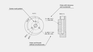
If there are threads in your parts, it is essential to clearly identify and define them on the technical drawing. Instead of specifying the diameter dimension, it is recommended to define the threads by indicating a standard thread size, such as M4x0.7. Providing detailed thread callouts is highly recommended as they enhance clarity in the drawing and enable the specification of pilot holes and threads with varying lengths.
the initial operation
For this particular scenario, the initial operation should define the dimensions of the pilot hole, which can be determined from standard tables. The second operation should focus on specifying the dimension and tolerance of the thread.
Could you explain the process of specifying tolerances in a technical drawing?
Tolerances
Tolerances play a crucial role in determining the acceptable range of values for a specific dimension of a part. They provide valuable insights into the functionality of the part, particularly for features that interact with other components.
CNC drawing
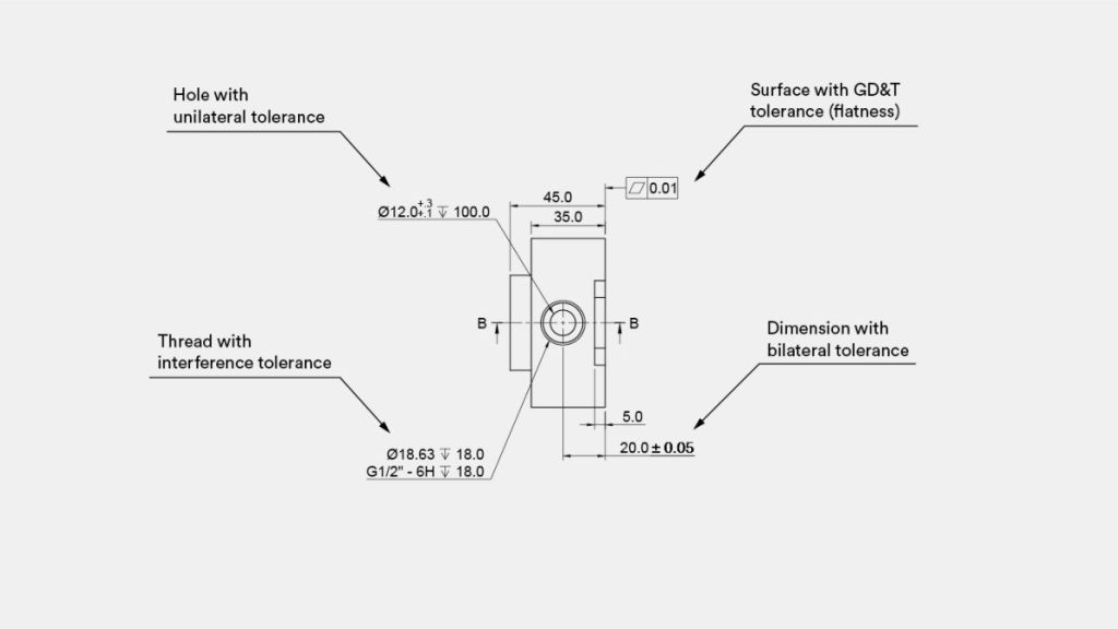
Various formats of tolerances exist and can be applied to any dimension on a CNC drawing, whether it is linear or angular. The simplest form of tolerance is bilateral tolerance, which is symmetrical around the base dimension (e.g., ± 0.1 mm). Additionally, there are unilateral tolerances that have different upper and lower limits, as well as engineering fit tolerances that are specified in the technical table (e.g., 6H). In the given example, a flatness tolerance (⏥) was defined.A more advanced way to define tolerances is GD&T (Geometric Dimensioning & Tolerancing).
Geometric Dimensioning & Tolerancing (GD&T) is a system used in engineering
GD&T
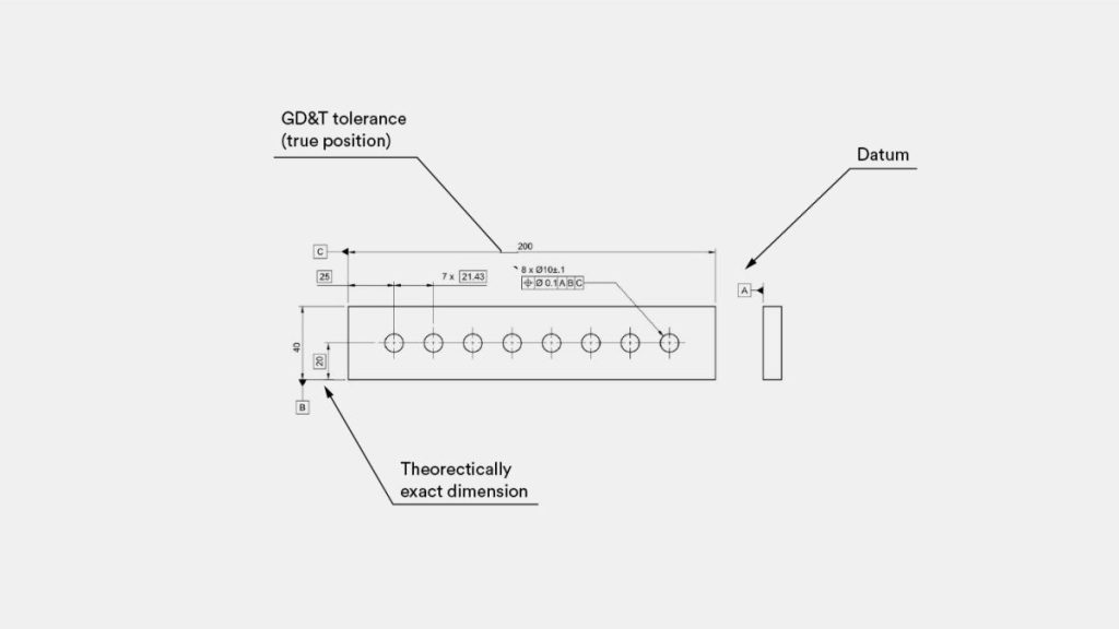
Manufacturing to define and communicate the allowable variations in form, size, and orientation of parts.cnc machining psrts.The implementation of the Geometric Dimensioning & Tolerancing (GD&T) system presents greater difficulties in comparison to conventional dimensioning and tolerancing.big cnc machining However, it is widely regarded as superior because GD&T effectively communicates engineering intent. By utilizing GD&T, it is possible to define broader tolerances while still meeting the primary design specifications. This not only enhances quality but also reduces costs. In the given example, the tolerance for this hole pattern was defined using true position (⌖). Other commonly used geometric tolerances include flatness (⏥) and concentricity (◎).
Here is an example of how to apply the GD&T system to a part design:
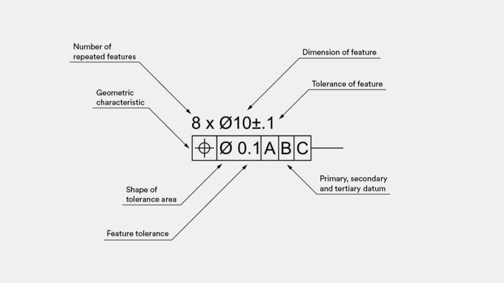
the GD&T system
Presented is a demonstration of implementing the GD&T system in part design: It should be emphasized that this specification indicates the existence of eight holes, each having a 10 mm nominal diameter and a tolerance of ± 0.1 mm.cnc machining tungsten This tolerance signifies that irrespective of the location where the diameter is measured, the measurement outcome must lie between 9.9 to 10.1 mm.cnc machining titanium
The true position tolerance, on the other hand, determines the precise location of the hole’s center in relation to the three main baseline edges (datum) of the part. This means that the center axis of the hole must always align with an ideal cylinder, centered at the location defined by the theoretically exact dimensions in the drawing, with a diameter of 0.1 mm.
In practical terms, this ensures that the center of the hole remains in its intended position, guaranteeing proper fitment with the rest of the assembly.
For critical assemblies and later stages of the design process, such as full-scale production, we recommend incorporating GD&T (Geometric Dimensioning and Tolerancing) information into your parts. However, it is important to note that these requirements have higher metrology standards, which can increase the cost of producing a one-off prototype.
