As a designer, you have arrived here to cut costs during the prototyping stage. The act of designing and the act of manufacturing are distinct forms of art. Designers strive for both functionality and aesthetics, while manufacturing engineers often face challenging geometries. Typically, the part is producible, but the expenses might escalate if the part was not initially designed with the manufacturing process in mind. Let’s focus on CNC aluminum parts and explore ways to minimize the expenses associated with aluminum processing.
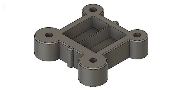
Prior to advancing your product to the prototyping stage, it is imperative to consider the subsequent recommendations. To exemplify these methodologies, I have opted for a shell model. This model entails a straightforward apparatus comprising of a panel seamlessly inserted into a square aperture, and the device securely fastened using four screws. Please refer to the accompanying image for visual reference.

Tip 1. Check the hole
1. Long thread
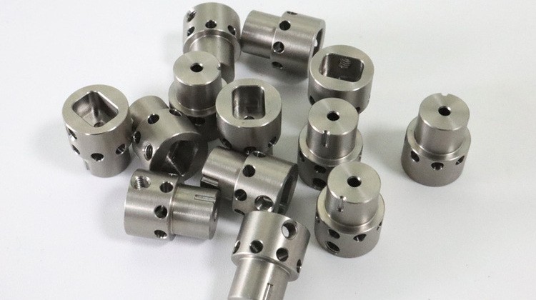
It is a widely held misconception that the greater the length of the thread and screw, the greater their holding force. However, this belief is completely incorrect. Upon careful calculation, it becomes evident that only the initial two or three teeth of the thread are capable of withstanding 80% of the force. Consequently, this implies that there is no necessity to create elongated holes for lengthy bolts.
2. Blind hole
If the hole is both blind and threaded, it is advisable to leave some unthreaded space towards the bottom of the hole. It is recommended to have at least two pitches of unthreaded space. The reason behind this is that the threading tool operates in two distinct zones. The first zone is known as the “cut in” zone. In this zone, the initial diameter of the tool matches the inner diameter of the thread. As the tool progresses, the diameter gradually increases to match the outer diameter of the thread. This gradual increase ensures that the tool cuts a little more with each turn. The second zone is utilized for calibration purposes. It helps in achieving a more precise thread. Consequently, the tool requires additional space to fully cut the last turn of the thread.
3.Find a deep hole
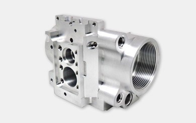
The general guideline states that the diameter should not exceed three times the size. This is because as the hole gets deeper, the drill bit becomes longer. Longer bits tend to be less sturdy and are more likely to deviate from the intended axis, resulting in lower quality holes. However, for such cases, a specialized tool called a gun drill is employed. It is capable of creating holes of almost any length, but it comes at a higher cost. Therefore, if your parts require deep holes, it may be worthwhile to explore this option. For instance, you could consider increasing the diameter if feasible, but only for the prototype. This approach would allow you to avoid the need for special equipment while still maintaining the primary functional characteristics of the part.
Tip 2. Check your pockets
1.90 degree Angle
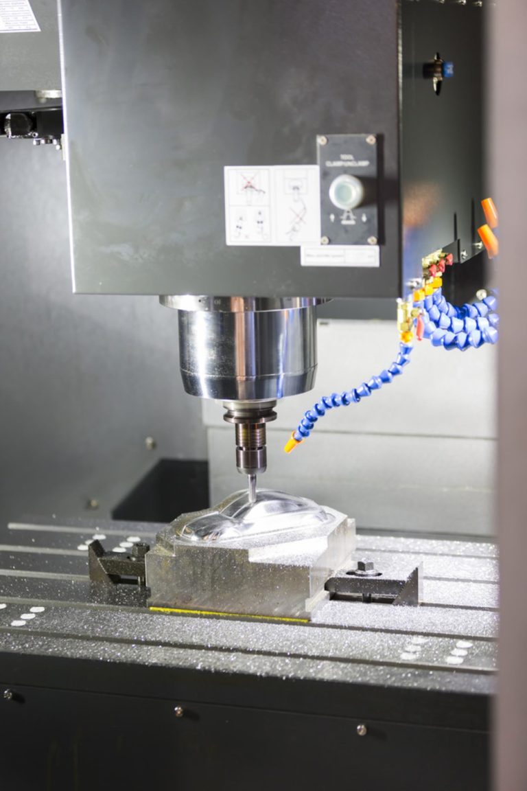
Parts with pockets are designed by individuals, and these pockets typically have a 90-degree angle. However, in prototype technology, most parts are machined using milling CNC centers. This process involves cutting chips from a blank using a cylindrical rotary tool. So, how is it possible to achieve a 90-degree angle in a limited space? The answer is simple: it is not possible. In order to adhere to the design, the manufacturer would need to utilize a shaping machine to remove the rounded corners. In many instances, this 90-degree angle is not even required, and only a fillet is necessary. Shaping the part in this manner is an unnecessary additional operation.
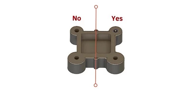
Certainly, there are instances where it is necessary to place certain components into the designated slot. However, it may be worth contemplating whether to incorporate rounded corners on these components to ensure a seamless fit. Adding rounded corners does not complicate or prolong the CNC program. If this is not feasible, you can opt to create a cylindrical cut that is a minimum of 1/3 the depth of the pocket (refer to the image provided). This will enable the manufacturer to machine the part on the milling machine while still accommodating the square component accordingly.
2.Avoid deep pockets
Oh, how foolish I was when I first started working! I was tasked with crafting a large turbine blade and had to shape an airfoil. Unfortunately, I made the mistake of selecting an inventory that was too small, resulting in the fixture being fixed at the edge of the airfoil. The pocket in the middle turned out to be quite deep due to its size and curvature, leaving me with limited movement around the wing perimeter. Any attempt to venture beyond that would have caused my spindle to collide with the jig, leading to a disastrous outcome. In order to proceed, I had no choice but to use a 150mm long 10mm grinder. However, I had to be extremely cautious with the cutting depth, as exceeding 0.3mm would cause the blade to snap like a brittle branch. Unfortunately, I ended up losing two or three milling tools while working on the wings. Therefore, the lesson learned here is to avoid small, deep pockets whenever possible. Otherwise, one must be prepared to invest in and potentially lose some tools.
3.Avoid thin walls
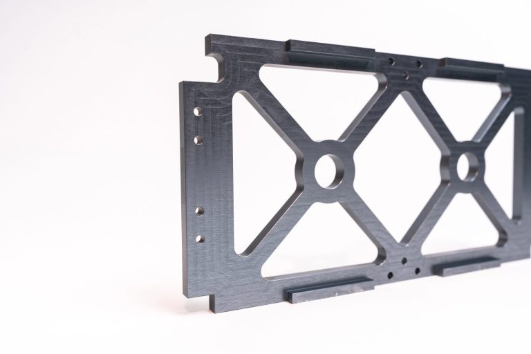
Slender partitions pose a challenge for manufacturers. The process of machining exerts significant force and generates heat. These delicate walls are susceptible to damage under such conditions. To reduce weight without compromising structural integrity, consider reinforcing thin components by increasing their thickness and incorporating holes. Alternatively, gradually increase the thickness of the wall as it approaches the base.
Tip 3. Check the part requirements
Numerous designers hold the belief that the higher the precision of a part or the smoother the surface finish, the superior the outcome. However, this notion is fundamentally flawed. Undoubtedly, polished and refined parts possess an appealing appearance, exhibiting a glossy finish and enhanced resistance against corrosion. Nevertheless, the production of such parts entails a lengthy and costly procedure. Hence, it is imperative to acknowledge the variation in part tolerances and surface finishes.
1.Inspection tolerance
Therefore, the narrative remains unchanged. If individuals fail to capitalize on this opportunity, what is the point of meticulously sanding and refining all surfaces to a precision of 0.005 mm? When creating a component, it is crucial to identify its functional surfaces and prioritize them.
2.Check the surface finish
In the field of manufacturing engineering, part surfaces are classified into two distinct categories: functional and secondary. The functional surface plays a crucial role in determining the operation of the parts within a mechanism. For instance, the internal center hole of a car wheel serves as a functional surface as it is directly mounted on the chassis. These surfaces are typically crafted with utmost precision and finesse, as they bear the entire load and perform all the necessary tasks.
Auxiliary surfaces, conversely, serve as a bridge connecting functional surfaces or are imperative for enhancing the structural integrity of components (thus augmenting their thickness). Consequently, it is not obligatory to ensure aesthetic appeal across all surfaces. Instead, one simply needs to allocate a fivefold increase in expenditure.
To sum up
There exist numerous methods for cutting down processing expenses. Certain methods entail precise dimensional alignment in the part blueprint, while others involve choosing or forming a surface to secure the part. Enhancing machining without altering the design is possible, and various intricate steps can be implemented. Nevertheless, product designers are not required to comprehend these techniques. It is the responsibility of manufacturing engineers to do so. However, since you are employed by an outsourcing firm, you must undertake some of their tasks during the design stage. Adhering to these guidelines will lead to a substantial decrease in the processing duration of your prototype.

